


 Home /
Custom Lithium Battery Pack for Medical Devices with NTC Temperature Monitoring


Table of Contents
- Why Medical Battery Temperature Must Be Evaluated at System Level
- NTC Selection Requires More Than a "10K" Specification
- Where Should the NTC Be Located?
- One NTC or Multiple NTCs for a 3S4P Pack?
- BMS, MCU or Fuel Gauge: Who Should Read the NTC?
- Temperature Thresholds Must Match the Selected Cell
- Current, Internal Resistance and Heat Are Directly Connected
- Validation Should Test the Complete Thermal Protection Chain
For a Custom Lithium Battery Pack for Medical Devices, temperature monitoring is not simply a matter of adding an NTC thermistor to the pack. The sensor must represent the real thermal condition of the cells, match the BMS or host electronics, and trigger the correct protection action under charging, discharge, fault, and enclosure-specific conditions.
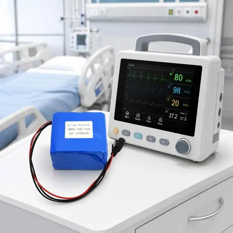
From Gloflux's engineering perspective, NTC monitoring should therefore be treated as part of the complete battery architecture: cell selection, electrical load, BMS, mechanical layout, wiring, communication, and device-level validation.
Why Medical Battery Temperature Must Be Evaluated at System Level
A battery that performs normally on an open test bench can behave differently after installation inside an infusion pump, patient monitor, or diagnostic device.
Typical heat sources include:
• Cell internal resistance during charging and discharge;
• BMS MOSFET and PCB losses;
• Pumps, motors, processors, and displays located near the battery;
• Restricted airflow inside compact enclosures;
• Insulation foam, shrink wrap, and structural parts that slow heat transfer.
The result is a thermal gradient: not every cell inside the battery reaches the same temperature.
This is especially relevant for a multi-cell Custom Lithium Battery Pack for Medical Devices, where one poorly positioned NTC may not detect the hottest area of the pack.
NTC Selection Requires More Than a "10K" Specification
An NTC thermistor changes resistance as temperature changes. However, specifying only "10K NTC" is insufficient for engineering or procurement.
A complete specification should include:
• R25 — nominal resistance at 25°C;
• B-value — defines the resistance-temperature curve;
• Resistance tolerance;
• B-value tolerance;
• Operating temperature range;
• Thermal response characteristics;
• Wire length and insulation;
• Connector and pin assignment.
Two 10K thermistors can have the same resistance at 25°C but produce different resistance values at 0°C, 45°C, or 60°C because their B-values differ.
The complete measurement path is:
Cell Temperature → NTC Resistance → Voltage Divider → ADC/BMS Reading → Firmware Logic → Warning Or Protection Action
An error at any stage can cause false over-temperature alarms, incorrect charging inhibition, or delayed thermal protection.
Where Should the NTC Be Located?
NTC placement should follow thermal testing rather than assembly convenience.
| Sensor location | What it measures best | Main limitation |
| Cell surface | Cell case temperature | May not represent another hotter cell |
| Pack center | Internal heat accumulation | Slower response in some structures |
| BMS/MOSFET area | Power-electronics heating | Does not represent cell temperature |
| Enclosure air | Ambient condition around pack | Can lag behind cell temperature |
For larger or higher-current packs, engineers may need more than one sensing point.
Adhesive thickness, foam, air gaps, insulation, and sensor contact pressure also affect the measured temperature. For this reason, Gloflux battery integration work can include customized wire length, connector configuration, casing, BMS, and mechanical layout rather than treating the NTC as an isolated component.
One NTC or Multiple NTCs for a 3S4P Pack?
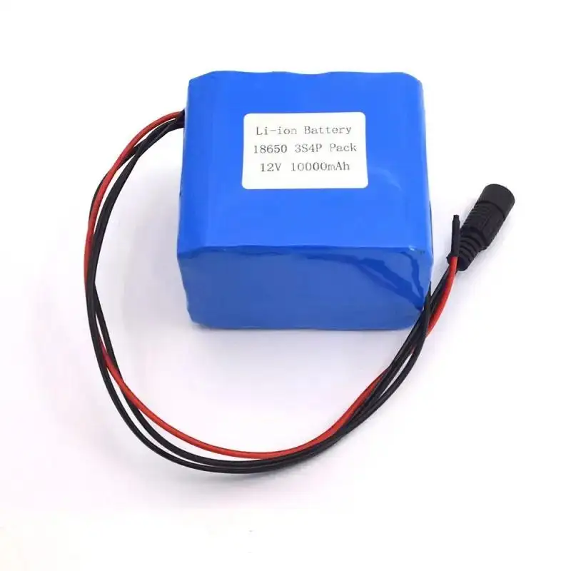
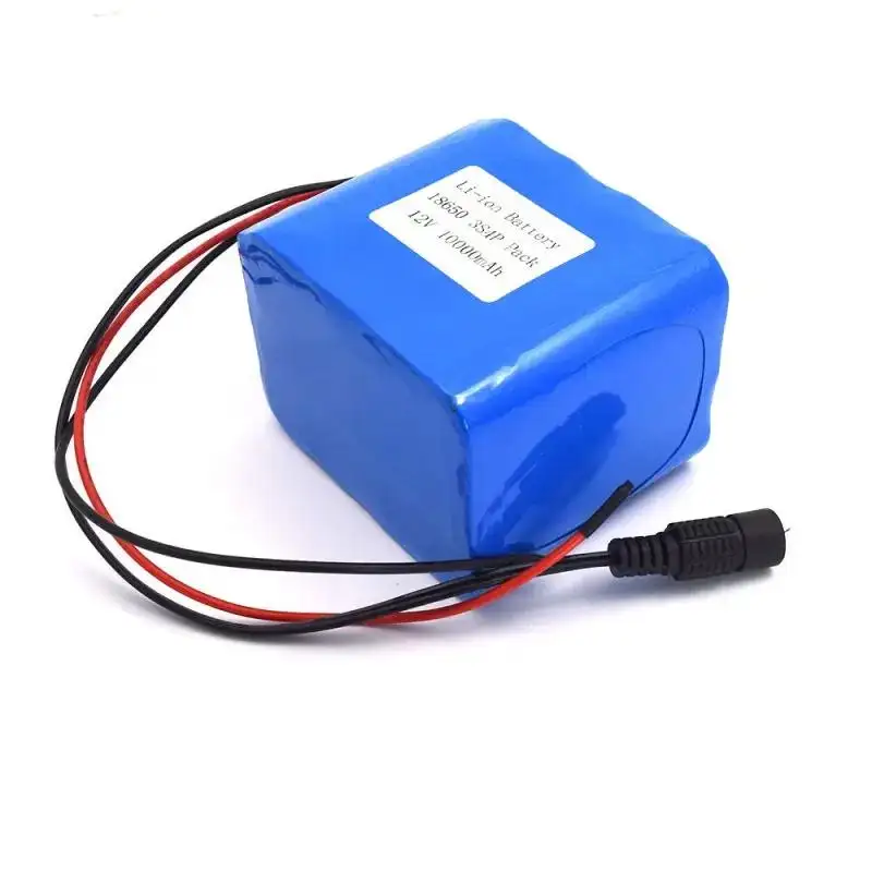
Gloflux's medical battery platform provides a useful example. The pack uses:
• 18650 cylindrical cells
• 3S4P configuration
• 12 cells total
• 11.1V nominal voltage
• 10,000mAh capacity
• 12.6V charging voltage
• 30A discharge current
• 120mΩ internal resistance
• 18 × 65mm cell dimensions
In a 3S4P arrangement, cells located near the center of the pack may dissipate heat differently from cells near the enclosure wall. Busbars, wiring, and current paths can also create localized heating.
Therefore, NTC quantity should be determined by:
• Thermal gradient across the pack;
• Expected continuous and peak current;
• Charging current;
• Enclosure design;
• BMS heat generation;
• Required fault-detection coverage.
A single NTC is acceptable only when thermal mapping confirms that its location represents the critical cell temperature.
BMS, MCU or Fuel Gauge: Who Should Read the NTC?
A Custom Lithium Battery Pack for Medical Devices can use several monitoring architectures.
NTC Connected to the BMS
This arrangement supports battery-side protection without relying entirely on the medical device software.
It is useful when the BMS must independently stop charging or discharge under an abnormal temperature condition.
NTC Read by the Host MCU
The medical device can use temperature data for:
• Warning messages;
• Charging control;
• Power reduction;
• Logging;
• Predictive maintenance.
However, designers must consider what happens if software freezes or communication is lost.
Dual-Layer Monitoring
For applications requiring stronger fault coverage, battery-side protection and host-side monitoring can be used together.
The key engineering question is not simply "Can the system read temperature?"
It is:
"Which component has authority to take protective action when the temperature exceeds the defined limit?"
Temperature Thresholds Must Match the Selected Cell
Generic temperature values should not be copied into a medical battery BMS.
Threshold development should follow:
Cell datasheet → Operating profile → Thermal testing → Risk assessment → Warning threshold → Cutoff threshold → Recovery threshold
Important settings include:
• Charge over-temperature cutoff;
• Charge under-temperature cutoff;
• Discharge over-temperature cutoff;
• Warning threshold;
• Protection delay;
• Recovery temperature;
• Hysteresis.
Charge and discharge limits do not necessarily need to be identical.
Hysteresis is particularly important because a BMS without sufficient separation between cutoff and recovery temperatures may repeatedly switch between normal and protection states.
Current, Internal Resistance and Heat Are Directly Connected
Battery heating increases with both current and resistance.
In simplified form:
Heat loss ∝ I²R
This means doubling current can increase resistive heating significantly.
For a Custom Lithium Battery Pack for Medical Devices, continuous current, short-duration pulse current, cell impedance, interconnect resistance, and BMS MOSFET resistance should therefore be evaluated together with temperature.
The Gloflux 11.1V 10Ah medical battery lists a 30A discharge capability, but the actual operating current for a medical device should always be defined from the real load profile rather than the maximum battery rating.
Validation Should Test the Complete Thermal Protection Chain
NTC verification should include more than checking resistance at room temperature.
A professional validation plan should evaluate:
• NTC resistance at multiple controlled temperatures;
• ADC or BMS temperature conversion accuracy;
• Sensor open-circuit and short-circuit faults;
• Warning and cutoff thresholds;
• Protection delay;
• Recovery and hysteresis;
• Charging under hot and cold conditions;
• Representative continuous and pulse loads;
• Final device enclosure conditions;
• Temperature distribution between cells.
Where applicable, battery and device developers should also evaluate requirements related to IEC 62133-2, UN 38.3, IEC 60601-1, and ISO 14971. These standards address different layers of battery safety, transportation, medical electrical equipment, and risk management; compliance with one does not automatically satisfy the others.
Designing the Battery Around the Medical Device
A reliable Custom Lithium Battery Pack for Medical Devices requires the cell pack, NTC, BMS, connector, wiring, enclosure, charging system, and device firmware to operate as one coordinated system.
Gloflux supports customization of voltage, capacity, connectors, wire length, casing, BMS, and communication functions for medical battery applications. Its 11.1V, 10,000mAh, 3S4P 18650 medical battery provides a practical starting point for projects requiring a pack adapted to the electrical, mechanical, and thermal requirements of the final device.
For medical equipment developers evaluating NTC monitoring, the most useful next step is to define the actual load profile, enclosure space, temperature limits, connector interface, and protection logic before finalizing the battery design. Gloflux can use those parameters to evaluate a Custom Lithium Battery Pack for Medical Devices around the real application rather than a generic battery specification.
FAQs
Q1. Can Gloflux customize a lithium battery pack for medical devices?
Yes. Gloflux can customize voltage, capacity, BMS, connectors, wire length, casing, and communication functions according to the electrical and mechanical requirements of the medical device.
Q2. What are the specifications of Gloflux's 3S4P medical battery pack?
The reference pack uses 12 × 18650 cells in a 3S4P configuration, with:
• Nominal voltage: 11.1V
• Capacity: 10,000mAh
• Charging voltage: 12.6V
• Discharge current: 30A
• Internal resistance: 120mΩ
• Cell dimensions: 18 × 65mm
Q3. Can Gloflux add NTC temperature monitoring to a Custom Lithium Battery Pack for Medical Devices?
Yes. NTC monitoring can be incorporated into a customized battery design according to the host device, BMS architecture, temperature-control strategy, connector interface, and sensor-placement requirements.
Q4. How does Gloflux determine where to place the NTC sensor?
NTC placement should be based on the pack structure, cell arrangement, current profile, enclosure design, and thermal distribution. The sensor should monitor a thermally representative or critical location rather than simply the easiest assembly point.
Q5. Can Gloflux customize the BMS for medical battery applications?
Yes. The BMS can be configured around application requirements such as overcharge, over-discharge, overcurrent, short-circuit protection, temperature monitoring, and communication functions.
Talk to the Manufacturer
Resources & Insights
High Capacity Lithium Battery for Wearables: High-Voltage LiPo Cell Design
2026-10-19
Cylindrical Battery Packs for Laptops: 2S vs 3S vs 4S Battery Design
2026-10-19
Stage Lighting Battery Pack: Prevent Voltage Drop & LED Flicker
2026-10-19

Best Rechargeable Batteries for Smart Devices: Performance, Safety, and Selection Guide
2026-10-19


