


 Home /
Custom Beauty Device Battery Manufacturer for USB-C Fast Charging


Table of Contents
- USB-C Does Not Define the Battery Charge Rate
- CC/CV Charging Sets the Real Charging Time
- 5V USB-C vs. USB-PD: Use the Architecture the Device Needs
- Linear and Switching Chargers Create Different Thermal Loads
- 3.7V and 7.4V Packs Require Different System Thinking
- Fast Charging Must Fit the Thermal Budget
- Protection PCB and Charger IC Perform Different Jobs
- Validate the Battery and Finished Beauty Device Separately
- What Gloflux Needs Before Battery Development Starts
USB-C is now common in portable RF, EMS, LED, facial cleansing, and skin-care devices. However, changing the connector does not automatically create a fast-charging product.
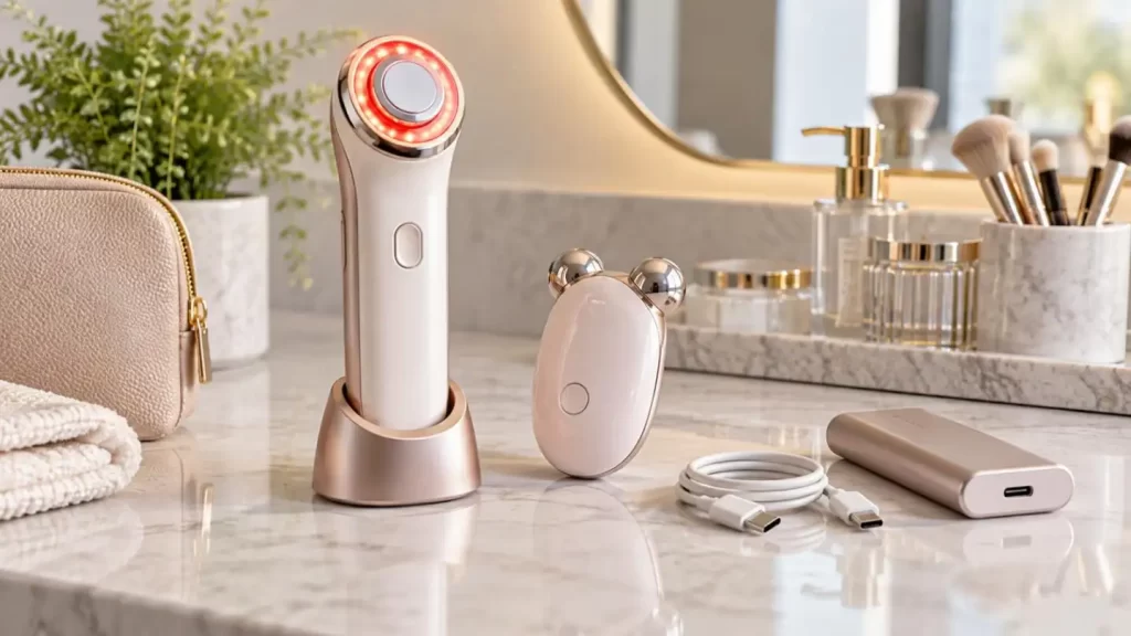
From Gloflux's perspective as a Custom Beauty Device Battery Manufacturer, USB-C charging must be engineered as one power system:
USB-C source → Charging controller → Charger IC → Protection circuit → Lithium cell → Thermal path
The limiting factor is rarely the wattage printed on the wall adapter. The real design limit is how much charging power the selected battery and compact beauty-device enclosure can safely manage.
USB-C Does Not Define the Battery Charge Rate
A beauty device may connect to a 20W, 45W, or even higher-power USB-C adapter, but the battery does not automatically receive that power.
Actual cell charging current depends on:
• USB-C or USB-PD negotiation
• Charger IC current limit
• Battery capacity and permitted charge C-rate
• Cell voltage
• Conversion efficiency
• NTC temperature feedback
• Device power consumption during charging
A useful engineering relationship is:
Charge C-rate = Charge Current ÷ Battery Capacity
| Battery Capacity | 0.5A Charge | 1.0A Charge | 1.5A Charge |
| 500mAh | 1C | 2C | 3C |
| 1000mAh | 0.5C | 1C | 1.5C |
| 2000mAh | 0.25C | 0.5C | 0.75C |
These values are mathematical examples only. They do not indicate that every cell is approved for each charge rate.
As a Custom Beauty Device Battery Manufacturer, Gloflux evaluates the selected cell specification, thermal environment, target charging time, and cycle-life requirement before defining the charging current.
CC/CV Charging Sets the Real Charging Time
Simply dividing battery capacity by charging current gives an unrealistic result.
Lithium batteries normally charge through:
Constant-Current Stage
The charger applies the programmed current while cell voltage rises.
Constant-Voltage Stage
Once the upper charging voltage is reached, voltage remains controlled while current gradually decreases.
This means a 1000mAh battery charged at 1A does not necessarily reach full charge in exactly one hour.
Real charging time also depends on:
• CV taper duration
• Temperature derating
• Charger efficiency
• Cable and connector losses
• Background system load
• Charge termination threshold
For portable beauty devices, optimizing the full charging curve is usually more valuable than simply maximizing peak charge current.

5V USB-C vs. USB-PD: Use the Architecture the Device Needs
USB-PD can provide higher and more flexible input power, but many compact beauty devices do not need a complex PD architecture.
| Design Factor | 5V USB-C | USB-PD |
| Circuit complexity | Lower | Higher |
| Controller requirement | Simpler | PD negotiation required |
| Available power range | Suitable for many compact devices | Better for higher-power systems |
| BOM cost | Lower | Higher |
| Typical fit | Small 1S packs | Larger packs or 2S designs |
| Main risk | Input-power limitation | Unnecessary complexity |
A small facial massager with a 500–1000mAh battery may gain little from a high-power PD input if the cell itself must charge at a relatively low current.
By contrast, USB-PD may become useful when the design includes:
• Larger battery capacity
• 2S battery architecture
• Higher charging power
• RF or LED circuitry operating during charging
• Shorter required charging time
A competent Custom Beauty Device Battery Manufacturer should therefore begin with the battery and system load, not with the highest available USB-C wattage.
Linear and Switching Chargers Create Different Thermal Loads
The charger topology can strongly affect enclosure temperature.
Linear Charger
Advantages include:
• Simple circuit
• Lower component count
• Small PCB footprint
However, the voltage difference between input and battery can be dissipated as heat.
Switching Charger
Advantages can include:
• Higher conversion efficiency
• Lower dissipation at higher charging power
• Better suitability for more complex voltage architectures
Trade-offs include:
• More components
• Larger design effort
• Switching-noise management
• More demanding PCB layout
This matters in beauty devices because the charger may sit close to the battery, motor, RF circuit, LEDs, or waterproof seals.
3.7V and 7.4V Packs Require Different System Thinking
Gloflux supports typical beauty-device battery configurations around 3.7V and 7.4V, as well as custom pack formats.
A 1S pack around 3.7V generally simplifies charging and protection, but RF, EMS, motors, or high-power LEDs may require additional voltage conversion.
A 2S pack around 7.4V provides a higher system voltage but introduces additional design requirements for:
• Series-cell management
• Pack protection
• Charging architecture
• Cell consistency
• Mechanical packaging
For a Custom Beauty Device Battery Manufacturer, voltage selection should therefore follow the device power architecture rather than being treated as an isolated battery specification.
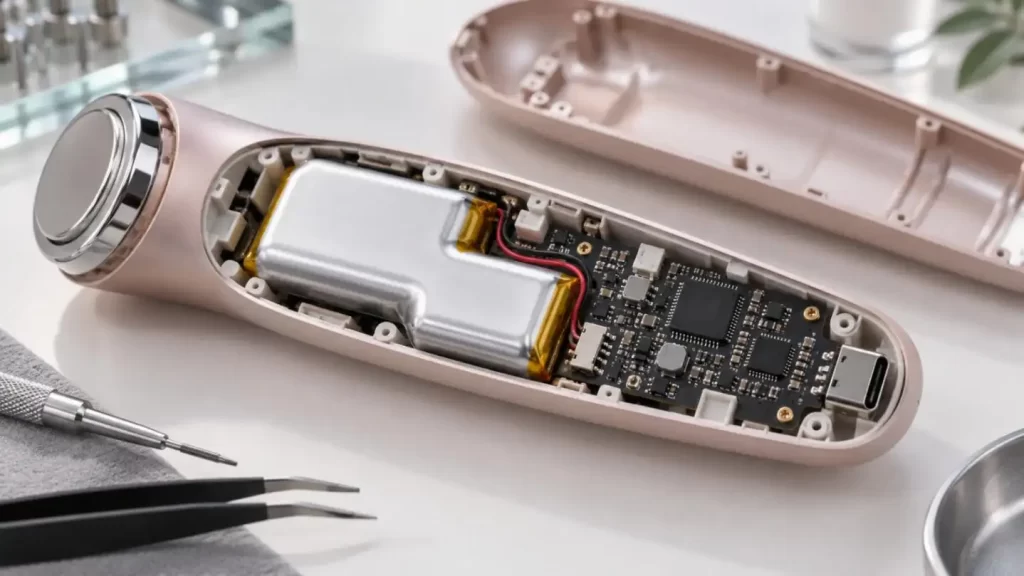
Fast Charging Must Fit the Thermal Budget
Higher current makes electrical resistance increasingly important because resistive heating approximately follows:
Heat ∝ I²R
Potential heat sources include:
• Battery internal resistance
• USB-C connector contacts
• PCB traces
• Charging IC
• Protection MOSFETs
• DC-DC converters
In a slim or waterproof beauty device, heat has fewer paths to escape.
Gloflux therefore considers battery integration together with:
• Cell-to-PCB spacing
• Pouch-cell swelling allowance
• NTC position
• Connector resistance
• Wire gauge
• Adhesive pressure
• Nearby heat-generating components
• Enclosure thermal path
This is particularly important for ultra-thin LiPo batteries, where mechanical pressure and insufficient swelling clearance can create long-term reliability problems.
Protection PCB and Charger IC Perform Different Jobs
A common design mistake is assuming that one circuit can replace the other.
The charger IC manages the charging profile, while the protection circuit may provide safeguards against conditions such as:
• Overcharge
• Over-discharge
• Overcurrent
• Short circuit
NTC sensing adds another layer by allowing charging current to be reduced or stopped when temperature moves outside the permitted range.
As a Custom Beauty Device Battery Manufacturer, Gloflux can integrate cells with customized protection boards, wires, connectors, insulation, and mechanical configurations according to device requirements.
Validate the Battery and Finished Beauty Device Separately
Battery qualification and finished-device compliance are not the same process.
Typical validation considerations include:
| Validation Area | Main Purpose |
| IEC 62133-2 | Rechargeable lithium-cell and battery safety |
| UN38.3 | Lithium battery transport testing |
| USB-C / PD validation | Power negotiation and interface behavior |
| Thermal testing | Cell, charger, PCB, and enclosure temperature |
| Cycle testing | Capacity retention under defined charge/discharge conditions |
| Device safety testing | Finished-product compliance for the target market |
Certification requirements should always be confirmed for the exact battery configuration, device type, and destination market.
What Gloflux Needs Before Battery Development Starts
For efficient engineering evaluation, beauty-device brands should provide:
• Available battery cavity dimensions
• Nominal operating voltage
• Average and peak current
• Required runtime
• Target charging time
• USB-C or USB-PD architecture
• Maximum acceptable temperature
• PCB and connector location
• Waterproof requirements
• Target cycle-life conditions
• Operating-temperature range
• Destination markets
• Prototype and production quantity
Gloflux operates a 30,000 m² manufacturing facility with more than 800 employees, approximately 350,000 units of daily capacity, and annual lithium-battery production exceeding 100 million units. Its capabilities cover cell selection, protection/BMS development, prototype verification, testing, custom LiPo formats, cylindrical lithium-ion solutions, and mass production.
For portable RF, EMS, LED, cleansing, or facial-care devices, involving a Custom Beauty Device Battery Manufacturer early can reduce later redesign around charging time, heat, battery dimensions, and certification. Gloflux can evaluate the electrical load, available space, charging target, and market requirements to develop a battery solution matched to the complete device rather than to a single USB-C specification.
FAQs
Q1. Can Gloflux customize batteries for USB-C beauty devices?
Yes. Gloflux can develop custom lithium battery packs according to the device voltage, capacity, dimensions, current demand, charging target, connector and protection requirements.
Q2. What beauty devices can Gloflux battery solutions support?
Gloflux battery solutions can be developed for portable RF devices, EMS beauty tools, facial cleansing brushes, LED skincare devices, massagers and other rechargeable personal-care products.
Q3. Can Gloflux develop ultra-thin LiPo batteries for slim beauty devices?
Yes. As a Custom Beauty Device Battery Manufacturer, Gloflux supports ultra-thin and custom-shaped LiPo battery designs for products with limited internal space.
Q4. Does Gloflux support both 3.7V and 7.4V beauty-device batteries?
Yes. Gloflux can support typical 3.7V single-cell and 7.4V multi-cell configurations, depending on the device power architecture and load requirements.
Q5. Can Gloflux design a battery for USB-C fast charging?
Gloflux can select and configure battery cells around the required charge current, C-rate, thermal limits and charging time. The complete USB-C charging architecture should also be matched with the device charger circuit.
Talk to the Manufacturer
Resources & Insights
High Capacity Lithium Battery for Wearables: High-Voltage LiPo Cell Design
2026-10-19
Cylindrical Battery Packs for Laptops: 2S vs 3S vs 4S Battery Design
2026-10-19

Stage Lighting Battery Pack: Prevent Voltage Drop & LED Flicker
2026-10-19

Best Rechargeable Batteries for Smart Devices: Performance, Safety, and Selection Guide
2026-10-19


